
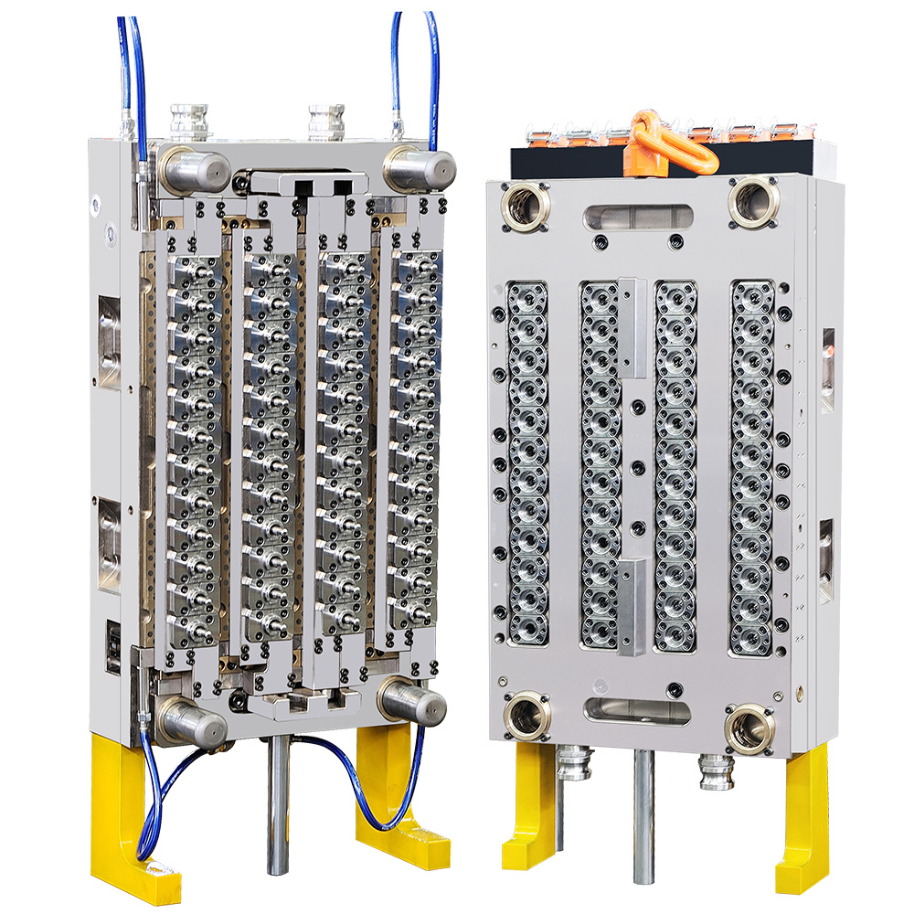
How to Perfectly Match Your Preform Mold with Your Injection Molding Machine
A Comprehensive Engineering Guide on Tonnage Calculation, Shot Size Ratio, Tie-Bar Clearance, and Hydraulic-Thermal Integration by GTWMOULD
Introduction: The Engineering Necessity of Tool-to-Machine Integration
In high-cavitation Polyethylene Terephthalate (PET) bottle preform injection molding, purchasing a high-grade mold is only half the battle. Delivering maximum output, achieving sub-10-second cycle times, and maintaining strict dimensional stability require absolute alignment between the PET preform mold and the injection molding press. Mismatches between mold geometry and machine specifications cause severe operational issues—including platen deflection, parting line flash, thermal degradation, short shots, and catastrophic core misalignment.
Evaluating compatibility requires deep engineering calculations across mechanical, hydraulic, pneumatic, and thermal interfaces. As an industry-leading Chinese manufacturer and high-precision PET preform tooling solution provider, GTWMOULD designs custom preform molds engineered for seamless integration with major global injection molding machinery brands (including Husky, KraussMaffei, Netstal, Engel, and Haitian). This comprehensive technical guide details the critical calculations and engineering parameters required to perfectly match your preform mold with your injection molding machine.
1. Clamping Tonnage Calculation and Projected Area Analysis
Insufficient clamping force causes the mold parting line to flash under peak cavity injection pressures ($1000\text{--}1500 \text{ bar}$), resulting in damaged tool steel and preform weight variations. Conversely, excessive clamping force crushes parting line vents, restricting air evacuation and causing burn marks or short shots.
Mathematical Clamping Force Calculation
Required clamping force ($F_c$) is determined by the total projected cavity area ($A_{\text{total}}$) multiplied by the peak internal cavity pressure ($P_{\text{cavity}}$), incorporating a safety factor ($K_s \approx 1.1\text{--}1.2$):
$$F_c = \frac{N \times A_{\text{single}} \times P_{\text{cavity}} \times K_s}{10,000}$$
Where:
- $F_c$: Required Clamping Force in Metric Tons ($\text{tonnes}$)
- $N$: Total Number of Cavities (e.g., 48, 72, 96, 128 drops)
- $A_{\text{single}}$: Projected Cross-Sectional Area of a Single Preform Body and Flange ($\text{cm}^2$)
- $P_{\text{cavity}}$: Average Internal Cavity Pressure ($400\text{--}600 \text{ bar}$ or $\text{kg/cm}^2$ during packing phase)
GTWMOULD performs structural Finite Element Analysis (FEA) to ensure clamping force is distributed evenly across all cavity drops, preventing platen bowing and localized steel compression.
2. Plasticizing Capacity, Barrel Shot Size, and Melt Residence Time
Matching the machine's injection cylinder volume with total shot weight is critical for maintaining PET polymer integrity and Intrinsic Viscosity (IV).
The Golden Shot Volume Rule: 35% to 75% Barrel Utilization
Total shot weight ($W_{\text{shot}}$)—including preforms and valve gate hot runner volume during startup—must consume between 35% and 75% of the machine's maximum shot capacity ($W_{\text{max}}$):
$$0.35 \le \frac{W_{\text{shot}}}{W_{\text{max}}} \le 0.75$$
| Capacity Ratio Metric | Operational Condition | Polymer Processing Risk | GTWMOULD Technical Remedy |
|---|---|---|---|
| Shot Ratio $< 30\%$ | Excessive barrel residence time ($> 5 \text{ minutes}$). | Thermal degradation, severe IV drop, resin yellowing, and Acetaldehyde (AA) spikes ($> 3.0 \text{ ppm}$). | Downsize injection unit barrel or increase mold cavitation count. |
| Shot Ratio $> 80\%$ | Insufficient screw plasticizing length and thermal soak time. | Unmelted resin crystalline core, temperature non-uniformity, high shear heating, and short shots. | Upgrade to a larger L/D ratio screw ($22:1\text{--}24:1$) or lower cavitation footprint. |
| Optimal ($35\%\text{--}75\%$) | Homogeneous melt plasticization with minimal thermal stress. | Preserved polymer IV, crystal clarity, and AA controlled strictly under $1.8 \text{ ppm}$. | Standard GTWMOULD low-shear hot runner integration. |
3. Physical Machine Interface and Mechanical Alignment
Proper physical fitment ensures that the mold operates smoothly without interference during high-speed opening, ejection, and robot take-out cycles.
Essential Physical Checklist
- Tie-Bar Clearance ($H_{\text{clearance}} \times V_{\text{clearance}}$): The overall length and width of the mold backing plates must pass cleanly between the horizontal and vertical tie-bars during installation.
- Mold Height Envelope ($H_{\text{min}} \le H_{\text{mold}} \le H_{\text{max}}$): Total stack height of the mold must fall strictly within the press platen adjustment range.
- Locating Ring & Sprue Bushing Radius: Machine stationary platen locating ring diameter must align precisely with the mold locating ring ($\pm 0.01 \text{ mm}$ fit) to center the hot runner sprue inlet with the machine nozzle tip.
- Ejector Stroke and Pattern: Hydraulic machine ejector rod locations must align with the mold stripper plate mechanical knock-out points to prevent uneven stripping motion.
4. Auxiliary Systems Synergy: Cooling, Hydraulics, and Pneumatics
1. Thermal Energy Extraction & Chiller Capacity
PET preform cooling accounts for over 60% to 70% of the total injection cycle time. Chilled water supply ($6^\circ\text{C}\text{--}8^\circ\text{C}$) must provide turbulent flow velocity ($Re > 4000$) through all cavity spiral channels and core bubblers. Required refrigeration capacity ($Q$) is calculated as:
$$Q = \dot{m} \times C_p \times \Delta T$$
Where $\dot{m}$ is hourly PET throughput ($\text{kg/hr}$), $C_p$ is PET specific heat capacity ($1.3\text{--}1.4 \text{ kJ/kg}\cdot^\circ\text{C}$), and $\Delta T$ is melt-to-ejection temperature delta ($\Delta T \approx 200^\circ\text{C}$). GTWMOULD inserts press-fitted hyper-conductive Beryllium-Copper (BeCu) alloys in high-heat gate zones to maximize heat transfer rates.
2. Pneumatic Pressure for Valve Gate Actuation
Synchronized valve gate hot runners require clean, dry compressed air at $6.0\text{--}8.0 \text{ bar}$ pressure to drive pneumatic cylinders, guaranteeing crisp, flush gate shut-off ($\le 0.2 \text{ mm}$ vestige).
5. Sub-Micron Precision Metallurgy & Component Alignment
GTWMOULD builds tools with certified materials and sub-micron machining tolerances to match demanding, continuous high-speed press operations:
- Certified Swedish S136 Stainless Steel: Vacuum-hardened to $48\text{--}52 \text{ HRC}$ across all core and cavity inserts for complete protection against corrosive polymer outgassing and cooling channel scale buildup.
- Triple-Taper Component Alignment System: Maintains core-to-cavity concentricity within:
$$\Delta \le 0.015 \text{ mm}$$
This restricts wall thickness variation under $0.025 \text{ mm}$, preventing core pin deflection even under maximum machine injection pressures. - Diamond-Like Carbon (DLC) Slide Coatings: Enables clean, oil-free mechanical movement on neck splits, eliminating lubricant contamination on preform threads.
Conclusion: Achieve Seamless Machine Integration with GTWMOULD
Understanding **How to Perfectly Match Your Preform Mold with Your Injection Molding Machine** shows that achieving peak production performance requires balancing mechanical tolerances, polymer rheology, thermal chilling capacity, and clamping dynamics. As a specialized engineering partner, **GTWMOULD** provides complete pre-production compatibility evaluations, ensuring your PET preform mold integrates flawlessly with your machinery for long-term productivity and lowest unit cost.
Contact GTWMOULD's technical engineering team today to audit your injection press specifications and receive a tailored high-performance tooling proposal.