
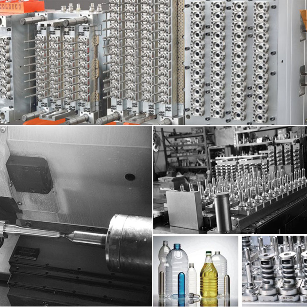
How Mold Flow Analysis (Moldflow) Optimizes Preform Design Before Steel Is Cut
A Technical Guide to Computer-Aided Engineering, Rheological Simulation, and Risk Mitigation in High-Cavitation PET Preform Tooling by GTWMOULD
Introduction: Virtual Validation in High-Precision PET Tooling
In high-speed Polyethylene Terephthalate (PET) preform injection molding, cutting tool steel without rigorous digital simulation carries substantial financial and operational risk. Minor geometric imbalances, non-uniform wall thickness profiles, or suboptimal runner channel diameters can result in catastrophic production failures, such as severe wall eccentricity, elevated Acetaldehyde (AA) levels, gate hazing, and short shots across peripheral cavities.
Modifying hardened steel after tool manufacturing increases development costs and delays time-to-market. As a premier Chinese engineering manufacturer and specialized solution provider, GTWMOULD integrates advanced Computer-Aided Engineering (CAE) and Mold Flow Analysis (Moldflow) into the pre-production workflow. By simulating polymer rheology, thermal dissipation, and pressure distribution before cutting steel, GTWMOULD delivers right-first-time high-cavitation PET preform molds built for maximum efficiency and long-term reliability.
1. Core Capabilities of Mold Flow Simulation in PET Processing
PET melt exhibits non-Newtonian, shear-thinning behavior under high injection pressures ($1000\text{--}1500 \text{ bar}$) and temperatures ($270^\circ\text{C}\text{--}290^\circ\text{C}$). Moldflow software models non-isothermal polymer flow through complex tool geometry, predicting melt front progression, shear stress rate, shear heating, and thermal contraction before tool steel fabrication.
Primary Parameters Analyzed During Virtual CAE Prototyping
- Melt Front Velocity & Filling Balance: Tracks melt progression across all cavities (from 24 to 128 drops) to guarantee simultaneous cavity filling without local pressure spikes.
- Shear Rate and Thermal Degradation: Identifies localized shear heating points within hot runner nozzles and valve gate tips to keep Acetaldehyde (AA) generation strictly under $1.8 \text{ ppm}$.
- Volumetric Shrinkage and Distortion: Calculates thermal contraction during cooling to prevent core pin deflection and preform body ovality.
- Air Entrapment and Venting Layout: Locates air traps to optimize micro-venting channel placement along parting lines and neck splits.
2. Resolving Critical Molding Defects Before Steel Fabrication
| Potential Molding Defect | Physical Mechanism / Cause | Moldflow Diagnostic Simulation | GTWMOULD Pre-Cut Design Optimization |
|---|---|---|---|
| Short Shots & Flow Marks | Uneven flow resistance across multi-drop runners and premature melt front freezing. | Isochrone filling analysis mapping pressure drop ($\Delta P$) across cavity drops. | Re-engineered naturally balanced hot runner manifolds with customized channel diameters. |
| Wall Thickness Eccentricity | Core pin deflection caused by asymmetric melt filling pressure forces. | Structural displacement and transverse force vector calculation on core pins. | Implementation of a proprietary triple-taper self-locking component alignment system. |
| Gate Hazing / Crystallization | Slow thermal extraction around the gate zone keeping resin in the crystallization window ($120^\circ\text{C}\text{--}180^\circ\text{C}$). | 3D transient cooling and thermal flux simulation near the gate base. | Integration of press-fitted hyper-conductive Beryllium-Copper (BeCu) gate inserts. |
| High Cycle Times | Inadequate heat transfer rates along thick preform wall transitions. | Volumetric temperature state analysis post-packing phase. | Design optimization of high-pitch spiral cavity cooling channels and high-velocity core bubblers. |
3. Mathematical and Rheological Principles in GTWMOULD Simulation
During simulation, polymer flow through the hot runner manifold and cavity geometry is governed by the conservation equations of mass, momentum, and energy:
$$\rho \left( \frac{\partial \mathbf{u}}{\partial t} + \mathbf{u} \cdot \nabla \mathbf{u} \right) = -\nabla P + \nabla \cdot \boldsymbol{\tau} + \rho \mathbf{g}$$
Where $\rho$ represents melt density, $\mathbf{u}$ is velocity vector, $P$ is pressure, and $\boldsymbol{\tau}$ is the shear stress tensor derived from non-Newtonian viscosity models (e.g., Cross-WVF model). By accurately mapping shear-thinning viscosity variations under extreme strain rates, GTWMOULD engineers optimize runner channel diameters to maintain identical pressure drops across all drops:
$$\Delta P_{\text{drop}_1} = \Delta P_{\text{drop}_i} = \Delta P_{\text{drop}_N} \quad (i = 1, 2, \dots, N)$$
This rheological balancing eliminates the need to force-fill peripheral cavities with elevated injection pressure, protecting resin integrity and extending tool lifespan.
4. GTWMOULD Precision Tooling Integration & Quality Assurance
Translating digital simulation data into physical tooling performance requires certified materials and sub-micron manufacturing accuracy:
- Certified Swedish S136 Stainless Steel: All cavity stacks, core pins, and neck split rings are machined from electro-slag remelted (ESR) S136 stainless steel, vacuum-hardened to $48\text{--}52 \text{ HRC}$ for superior corrosion resistance and high-polish longevity.
- Sub-Micron Concentricity Control: FEA-guided core locking guarantees core-to-cavity concentricity within:
$$\Delta \le 0.015 \text{ mm}$$
This restricts wall thickness variation under $0.025 \text{ mm}$ across all cavities. - High-Velocity Turbulent Cooling: CAE-optimized spiral cooling channels ensure turbulent water flow ($Re > 4000$), enabling rapid heat extraction and sub-10-second cycle times on lightweight preforms.
- Oil-Free Operation: Diamond-Like Carbon (DLC) slide coatings on neck split components enable clean mechanical movement without lubricant risk on preform thread finishes.
Conclusion: Right-First-Time Tooling Engineering with GTWMOULD
Understanding **How Mold Flow Analysis (Moldflow) Optimizes Preform Design Before Steel Is Cut** emphasizes that high-performance preform tooling relies on scientific engineering rather than trial-and-error machining. By combining predictive CAE rheological simulation with sub-micron component manufacturing, hyper-conductive thermal management, and premium tool metallurgy, **GTWMOULD** delivers industry-leading PET preform molds designed for maximum productivity and lowest unit manufacturing cost.
Contact GTWMOULD's technical engineering team today to perform a comprehensive Moldflow evaluation for your next PET preform tooling project.