
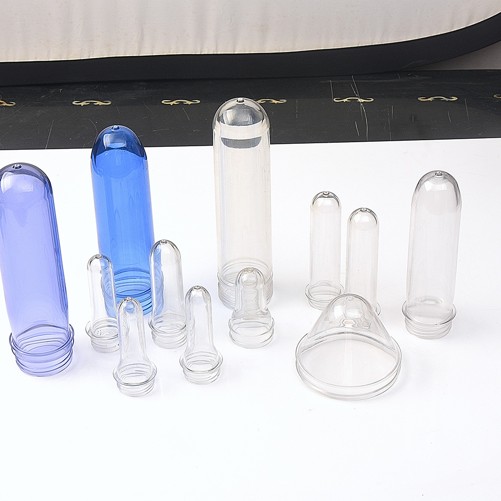
Achieving Preform Wall Thickness Uniformity: Design Principles and Process Control
Wall thickness uniformity in PET preforms is not a cosmetic specification. It is the foundational variable that determines whether a bottle will blow to consistent dimensions, maintain top-load strength, and pass drop testing at target weights. For preform molders running thin-wall designs—particularly as lightweighting pushes average wall thickness toward 1.4 mm and below—the margin for thickness variation collapses rapidly [citation:3].
At GTWMOULD, a China-based manufacturer specializing exclusively in PET preform molds, we have observed that thickness uniformity failures rarely originate from a single cause. They emerge from the interaction between mold design decisions, hot runner balance, cooling architecture, and injection process control. This article examines each layer of that system and the engineering principles that govern them.
The Physics of Non-Uniform Wall Thickness: Where Variation Originates
Before examining solutions, it is worth understanding where thickness variation physically originates in a preform mold. Molten PET enters the cavity through a gate, typically positioned at the base of the preform. As the melt flows axially toward the neck, it loses heat to the cold cavity walls and core surfaces. The pressure required to complete the fill increases as the effective flow channel narrows—a relationship that becomes critical as preform walls thin [citation:11][citation:12].
Two mechanisms drive thickness non-uniformity:
Flow-induced variation. If the hot runner system delivers melt unevenly across cavities, or if the gate geometry creates asymmetric flow, the polymer fills some regions faster than others. The faster-flowing regions experience less cooling during fill, pack more efficiently, and end up thicker. Slower regions may pack inadequately, yielding thin walls and potential short shots.
Cooling-induced variation. Even with perfect fill, differential cooling rates across the preform surface create differential shrinkage. The gate area, surrounded by relatively cool mold steel, solidifies first. The body section, with more thermal mass, cools more slowly. If the core and cavity cooling circuits do not compensate for these differences, the resulting shrinkage gradient manifests as wall thickness variation [citation:7].
Design Principle 1: Core Geometry and Thermal Management at the Gate
The core—often called the mandrel—is the most thermally demanding component in a preform mold. It must extract heat from the inside of the preform while maintaining dimensional stability across millions of cycles. The gate area, where the preform base is thickest and the melt is hottest, is the critical zone.
Patent literature on preform core design describes a fundamental technique: making the core wall thinner at the base end than along the body [citation:7]. A thinner core wall at the gate reduces thermal resistance, allowing heat to transfer more rapidly from the molten gate region to the cooling fluid inside the core. The same reference describes a bubbler cooling arrangement in which chilled coolant is delivered directly to the base end of the core through a central tube, with the coldest coolant contacting the hottest region first [citation:7].
GTWMOULD applies these principles through core designs that use variable wall thickness matched to the thermal load distribution across the preform length. Where gate cooling is critical—particularly for thick-walled preforms or high-IV resins—we employ bubblers with optimized flow paths to maximize heat extraction at the base without overcooling the body section.
Design Principle 2: Hot Runner Balance and Sequential Valve Gate Control
For multi-cavity preform molds—48, 72, 96 cavities and beyond—hot runner balance is not optional. It is the primary determinant of cavity-to-cavity thickness consistency.
A conventional hot runner manifold relies on geometrically balanced flow channels to distribute melt equally. For virgin PET under stable conditions, this can achieve acceptable balance. But as preform walls thin and cycle times shorten, the margin narrows. Research on injection molding parameters for PET preforms shows that holding pressure, packing time, and injection speed interact in ways that amplify any inherent imbalance [citation:15].
Sequential Valve Gate (SVG) hot runner systems address this by using pressure transducers at each gate to monitor cavity pressure in real time. The valve pin timing is adjusted dynamically to compensate for viscosity variations, flow imbalances, or temperature drift across the manifold. For preform molds where wall thickness tolerance is measured in hundredths of a millimeter, this active control layer provides a level of consistency that passive balancing cannot match.
GTWMOULD’s hot runner systems are engineered with fully balanced manifold designs and SVG capability for high-cavitation applications. The larger flow channels in our manifolds also reduce shear stress on the melt, which helps preserve intrinsic viscosity—a factor that becomes increasingly important as lightweighting pushes melt residence time closer to the degradation threshold [citation:2].
Design Principle 3: Cooling Channel Architecture
Cooling accounts for the majority of cycle time in preform injection molding, and it is also the primary lever for controlling wall thickness uniformity. The cooling equation for preforms shows that cooling time scales with the square of wall thickness [citation:16]:
tC = (w² / π²a) · ln[(8/π²) · (Ti − Ts) / (Td − Ts)]
where w is wall thickness, a is thermal diffusivity, Ti is injection temperature, Ts is cavity surface temperature, and Td is demolding temperature.
This relationship has two implications for mold design. First, thinner walls cool dramatically faster—which is why lightweighting is attractive for cycle time. Second, the cooling rate is not uniform across the preform because the effective wall thickness varies at the gate, body, and neck transition. If the cooling circuit design does not account for this variation, the preform will demold with residual temperature gradients that cause post-mold shrinkage and thickness drift.
GTWMOULD designs cooling circuits using computational flow analysis to ensure turbulent flow (Reynolds number above 10,000) throughout the circuit. Turbulent flow improves heat transfer coefficient by an order of magnitude compared to laminar flow. For the neck finish area, where dimensional precision is critical for cap sealing, we often use independent temperature control circuits to maintain the neck at a different temperature from the body.
Process Control: The Injection Parameters That Defend Thickness Uniformity
Mold design establishes the envelope. Process control determines whether production stays within it.
Published research on PET preform injection molding using Taguchi methods identifies several parameters with statistically significant effects on warpage and weight consistency [citation:15]:
Holding pressure and packing time. These parameters compensate for shrinkage as the melt cools. Insufficient holding pressure produces under-packed regions and wall thinning. Excessive pressure creates flash or over-packing at the gate. The optimal window narrows as wall thickness decreases.
Injection speed. Faster injection fills the cavity before significant cooling occurs, reducing the viscosity differential across the flow front. But excessive speed creates shear heating that can degrade PET and cause gate blush. The optimal injection speed for thin-wall preforms is typically in the range of 8–12 g/s, depending on resin grade and preform geometry [citation:16].
Melt temperature uniformity. The extruder barrel, nozzle, manifold, and gate must deliver melt at consistent temperature. Hot runner temperature variation of more than ±5°C across a multi-cavity manifold produces measurable thickness variation. GTWMOULD hot runner systems use zoned temperature control with independent thermocouples for each manifold section to maintain uniformity.
Verification: How Thickness Uniformity Is Measured and Confirmed
A preform mold is not validated until thickness uniformity is measured across the full production run, not just at startup.
Standard practice involves sectioning preforms at defined axial positions—typically near the gate, mid-body, and below the neck—and measuring wall thickness at multiple circumferential points. For a preform with nominal wall thickness of 2.0 mm, industry-acceptable variation is typically ±0.10 mm for standard applications, tightening to ±0.05 mm for high-performance or lightweight designs.
GTWMOULD includes measurement protocols in our mold validation documentation. We recommend sampling at regular intervals during the first production run, with data recorded for gate-side, mid-body, and neck-adjacent positions. This data establishes the process capability (Cpk) for the mold and identifies whether any cavities require gate adjustment or cooling circuit modification.
GTWMOULD: Preform Mold Engineering for Uniformity and Consistency
GTWMOULD manufactures PET preform molds with a singular focus: delivering the dimensional precision that consistent bottle production demands. Our engineering process integrates mold flow simulation, thermally balanced core and cavity design, SVG hot runner technology, and validation protocols that confirm wall thickness uniformity before the mold ships.
We serve preform molders producing containers for water, carbonated soft drinks, edible oil, pharmaceuticals, and household chemicals. Whether your application requires a 24-cavity mold for specialty containers or a 96-cavity system for high-volume water bottle production, GTWMOULD engineers the tooling architecture that makes wall thickness uniformity a design outcome, not a production variable.
Contact GTWMOULD to discuss your PET preform mold requirements or to request a technical evaluation of your current preform tooling.
Keywords: PET preform mold, preform wall thickness uniformity, PET preform mold manufacturer, preform tooling design, hot runner preform mold, PET injection mold, preform cooling technology, preform core design, GTWMOULD, China PET preform mold, SVG hot runner, preform wall thickness control, thin-wall preform mold